Consulting tools
Information tool
You can access the information tool via the following button in the tool bar

or by going to the “View” menu bar, to “Query” and then to “Information”.
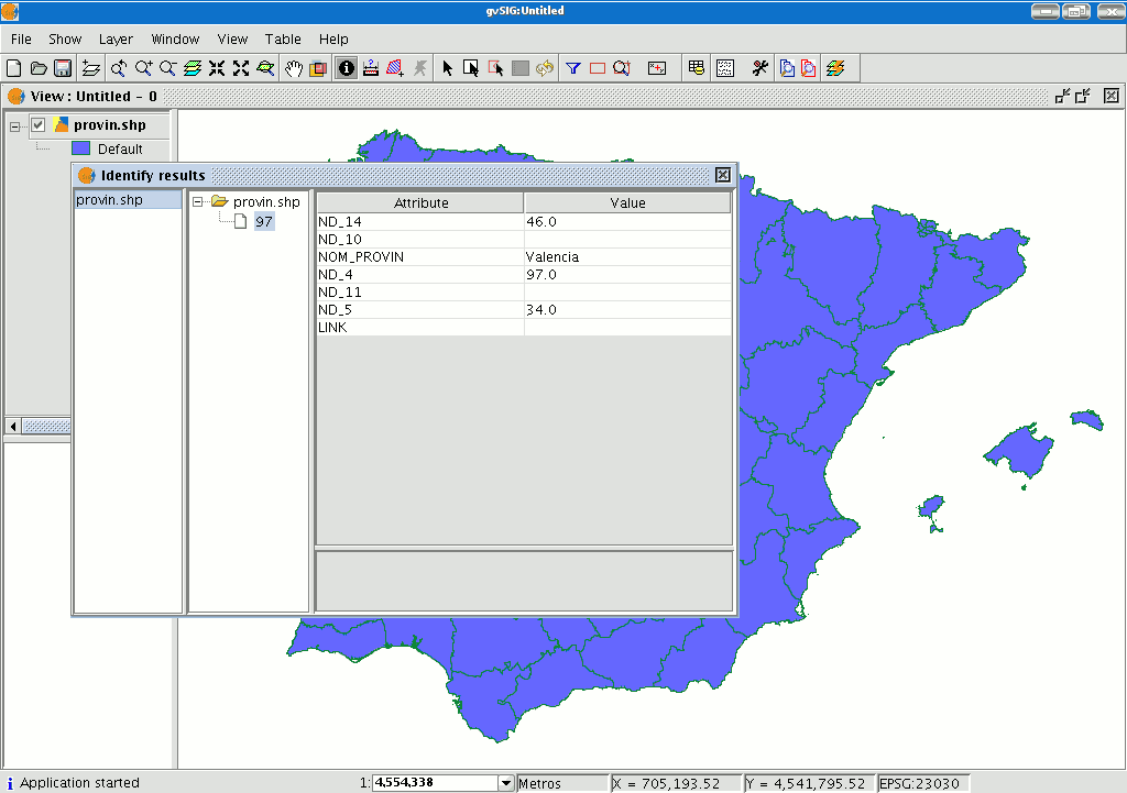
The “Information Tool” is used to obtain information about the map elements.
When you click on an element using this tool, gvSIG shows the selected element’s attributes in a dialogue window. However, the layer of the element you wish to identify must previously be activated.
Herramienta de información rápida
In gvSIG, this tool is used to quickly display available information when working with a view containing visible vector layers (including WFS layers, which are vector layers).
 Quick Info is enabled if vector layers are visible in the current view.
 Quick Info is disabled if no vector layers are visible in the current view.
With this tool you can select fields from vector layers visible in the current view. Information from these fields is displayed as you move the mouse cursor over the view. The tool works in combination with any other tools selected for the view.
You can access the Quick Info tool in two ways:
- Via the menu: View → Query → Quick Info
- Via the icon on the toolbar.
When the tool is selected a progress bar is displayed which shows the layers being loaded:
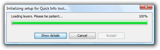
Progress bar for loading information
If there were no problems loading the information the Quick info field selection dialog is shown:
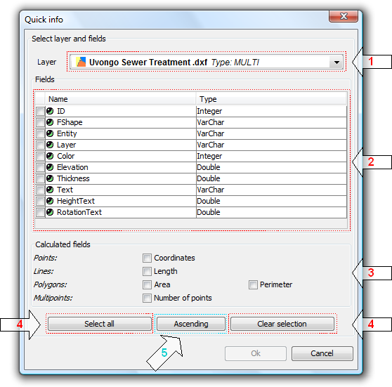
Dialog for the selection of fields
- Drop-down list for selecting vector layers. Lists the layers in the order that they appear in the TOC of the active view. The following information is shown:
Level of the Layer in the TOC: displays icons and grouping nodes  containing the layer. The last icon always represents the vector layer.
Name of the layer.
Type of geometry of the layer: five types of geometry layer are supported: point, line, polygon, multipoint, and multi (the latter may contain any of the above).
- List of Fields. Contains three columns:
- Selection box (checkbox): indicates whether or not to display the field information.
- Field Type + Field Name: the field type is represented by an icon as shown in the following table:
 The field type is simple.
- The field type is complex.
- Type of field: according to the SQL types.
- Calculated fields. List of checkboxes to select which geometry fields to calculate. These vary depending on the geometry of the layer:
- Point layer: point coordinates.
- Line layer: length of the line.
- Polygon layer: perimeter and area of the polygon.
- Multipoint layer: number of points.
- Multi-geometry layer: any of the above; the information will vary according to the selection and the nature of the geometry.
 The units of length and area are displayed using the measurement units of the View.
- Selecting / de-selecting all the fields in the layer. Select or de-select all the fields in the layer.
- Sort fields. Sort fields alphabetically in ascending or descending order, or according to the internal order of the layer (default).
After selecting the fields, click Ok to enable the tool in the current view. The Quick info tool works in combination with Quick info tools for other Views. Thus, when enabled, it combines with each active View to display information. The tool settings can be changed for each View and are linked to that View.
As the cursor is moved over the geometry of a layer, the information box showing the information is displayed and/or updated. This box disappears when the cursor no longer "points" to any geometry of the layer.
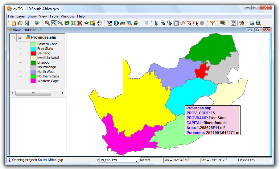
Example showing the display from the Quick info tool
If there is more than one geometry adjacent to the point indicated by the cursor then information is displayed about all of them, as distinguished by the unique internal identifier of the geometry.
Thus, the information is provided in the following order:
- Name of the layer.
- Information on the geometry (for each one):
ID: unique identifier of the geometry in the data source layer (optional, only visible if you have information on more than one geometry).
Selected fields: those fields selected to display layer information.
Optional fields: those calculated fields selected from the geometries of the layer.
 It should be noted that currently gvSIG adds the area and perimeter of islands to the geometry containing them.
Measuring areas
You can access this tool via the following button

or by going to the “View” menu and then to “Query” and “Measure area”.
This tool works in much the same way as “Measure distances”. Click on the point that represents the first polygon vertex that defines the area to be measured. Move the mouse and click on each new vertex until you reach the last one, then double click so that the application knows there are no more.
The calculation for the measured area appears at the bottom right of the view window.

Measuring distances

This tool provides information about the distance between two points. You can also access the tool by going to the “View” menu, to “Query” and then to “Measure distances”.

Firstly, make sure you have correctly defined the units of measurement (metres by default).
Remember that the units can be defined in the “Project manager” in the view properties or from the “View” menu and the “Properties” when working in a view.
You can use the measure distance tool by clicking on the mouse at the source point and dragging it to the destination point.
You can take as many measurements as you like. Double click on the last one to finish.
The calculation for the measured distance appears at the bottom of the view window. Both the distance of the last measured segment and the total distance are shown.
Catalogue. Searching for geodata
Introduction
The catalogue service allows you to search for geographic information on the Internet. gvSIG offers a user-friendly interface which allows you to find geodata and load it in the view, as long as the nature of the data allows this.
Connecting to a server
Before you can carry out a search, you will need to connect to a catalogue server. To access the wizard, you will first need to open a view and then click on the following button:

The first window of the catalogue opens. Input the required parameters to connect to a server. These include:
- The server address.
- The server protocol, which in the case of the catalogue can be:
- Z39.50: General information retrieval protocol.
- SRU/SRW: Variant of Z39.50.
- CSW: Catalogue protocol defined by the OGC in the “Catalogue Interface 2.0” specification.
- Data base name: You only need to indicate the data base you wish to connect to in the case of z39.50. If no value is input you will connect to the default data base.

Then click on the “Connect” button. If the connection is made and the server supports the specified protocol, a new window will appear to start the search.
Searching
To carry out a search, you need to fill in the fields that appear in the following form.
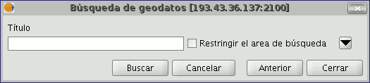
Click on the button and the window will drop down to show more fields which will allow you to carry out an advanced search. The fields you can search in are set by the server. This means that some of the search fields in this form may have no effect in some servers.
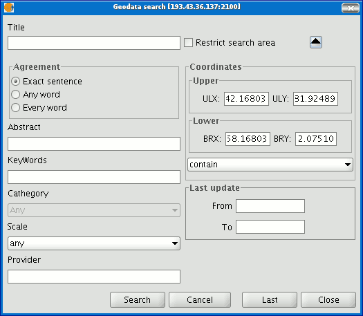
If you change the view zoom, the new coordinates will be reflected in this form. If you wish to restrict the search area enable the corresponding check box. Then click on “Search” and wait for the search to be carried out.
Viewing the results
If the search has been successful, a new window containing the search results will open.
Use the “Previous” and “Next” buttons to see each of the results obtained.
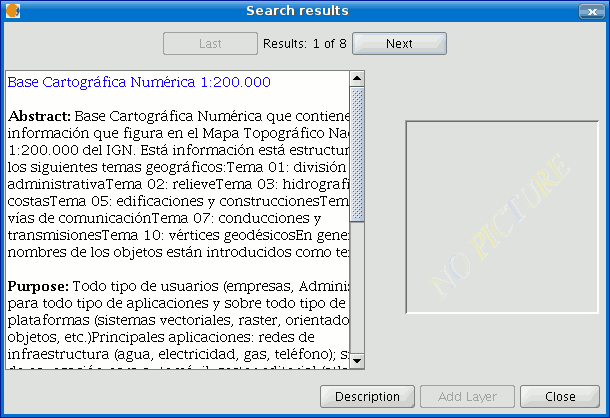
The left-hand side of the window shows information about the metadata obtained. If you wish to see all the information, click on the "Description" button.
You will also be able to see a miniature image at all times, metadata permitting.
If the metadata has any geodata associated to it, the “Add layer” button will be enabled.
gvSIG can currently recognise different types of associated resources, such as WMS, WCS, Postgis tables and web pages.
If you click on this button, a new window will be opened and will show all the resources the application has been able to find.
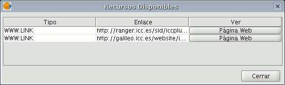
If you click on a WMS, WCS or Postgis type resource, the new layer will automatically be loaded in gvSIG. If the resource is a web page, for example, the operating system’s default browser.
Gazetteer
Introduction
A gazetteer is a data set in which a link is established between a toponym and its geographic coordinates.
gvSIG has a catalogue client which allows you to search by toponyms and centre the view on a specific point.
Connecting to a server
Create a view first and open it. The following button will appear automatically in the gvSIG tool bar.

Click on the button. A wizard opens to help you to carry out a search. The parameters to be input are:
- The server address.
- The server protocol, which in the case of the gazetteer can be:
- WFS-G: Toponym search protocol defined by the OGC.
- WFS: Although this protocol was created with a different purpose in mind, it can be used for a toponym search, as long as it has a text attribute in one of the tables. This protocol also allows you to carry out a “Feature” search in any other field, but not necessarily a text attribute.
- ADL: Protocol specified by the Alexandria Digital Library.
- IDEC/SOAP: Protocol that uses the Catalonian Cartographic Institute (ICC) gazetteer web service.
When you have input all the parameters, click on the "Connect" button and wait until the server is found and accepts the specified protocol. If it is accepted, a new window will appear to start the search. If not, an error message will appear.
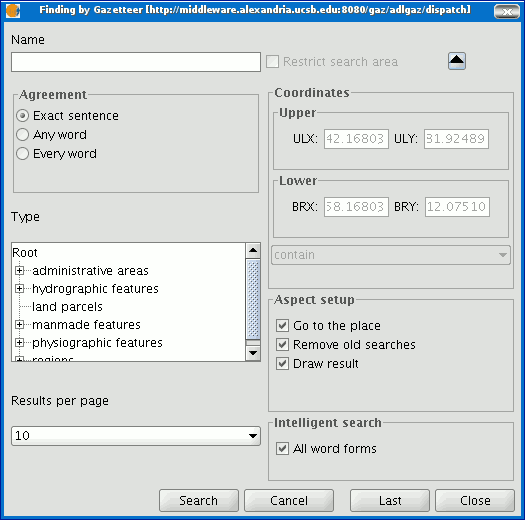
Searching
To carry out a search, you will need to fill in the criteria that appear in the following form. You can see the simplified form or carry out an advanced search by clicking on the button in the top right hand corner. This drops down the window.
If you change the view zoom, the new coordinates will be reflected in this form. If you wish to restrict the search area activate the corresponding check box. There are also three options in the “Aspect set up” box which you can use to set up the search view:
Zoom to search: This puts the toponym found in the centre of the gvSIG view.
Delete old searches: This deletes all the texts found in the previous searches from the view.
Draw result: This draws a point and a text label in the place the resulting toponym has been found.
When you have filled in all the fields in the form, click on “Search” and wait for the search to be carried out.
Viewing the results
A new window containing the search results will open. Use the “Previous” and “Next” buttons to move through the different pages of results.
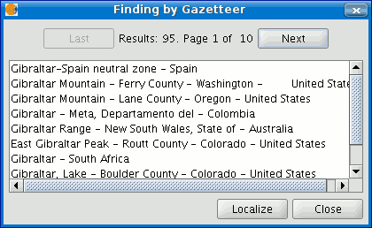
Finally, select the toponym required and click on “Localise”. The gvSIG view will centre on the point the toponym is located in.
Hiperenlace avanzado
The Advanced Hyperlink tool in this version of gvSIG significantly extends the functionality of the hyperlink tool found in version 1.1.
The tool is accessible either from the Layer menu (Layer > Advanced Hyperlink) or by clicking the icon on the toolbar.
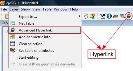
Accessing the Hyperlink tool
Hyperlinks are configured at the layer level, which means that they can be enabled or disabled per layer. To set the hyperlink for a layer, double-click on the layer name in the TOC to open the Layer Properties and select the Hyperlink tab.
The hyperlink configuration screen looks like this:
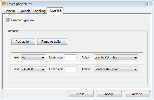
Hyperlink Configuration
Remember that the layer's attribute table must be correctly prepared for the hyperlinks to work. To do this, edit the relevant record and insert the path to the hyperlinked file, leaving out the extension.
After the hyperlinks have been setup and enabled, select the Advanced Hyperlink tool and find the item in the View that corresponds to the record associated with the link. Click on the item and a window will open displaying the linked file.
Actions
The Advanced Hyperlink tool provides the following actions:
- Link to text and HTML files: the tool will open a window in gvSIG and load the linked text or HTML document into it.
- Link to image files: the tool will open a window in gvSIG and load the linked image into it.
- Link to PDF files: the tool will open a window in gvSIG and load the linked PDF document into it.
- Load raster layer: the tool loads the raster layer into the active View.
- Load vector layer: the tool loads the vector layer into the active View.
- Link to SVG files: the tool will open a window in gvSIG and load the linked SVG file into it.
NOTE 1: When editing the hyperlink fields in the attribute table, if a path longer than the maximum field length is entered, the path will be truncated (without warning) to the maximum field length. By default, fields are created with a maximum length of 50 characters. Fields should be defined to handle long paths when necessary, otherwise only very short paths can be stored.
For example: if we enter
C:/Documents and Settings/My documents/images/villafafila.jpg
and the maximum field length is 50 characters, the path will be truncated to:
C:/Documents and Settings/My documents/images/vill
which is not what is wanted.
NOTE 2: Please note that if the path you enter contains an image or file extension that is registered in the registry, you should not also enter it when configuring the hyperlink properties as this would be duplicating the information.
